
NovaStar MRV412-N: Pixel Capacity, HUB75E and Calibration
Executive Summary: The NovaStar MRV412-N is a high-reliability, general-purpose LED receiving card engineered for commercial fixed installations and stage rental cabinets. Featuring an on-board integration of 12 standard HUB75E 16-pin connectors, it supports up to 24 groups of parallel RGB data and drives a maximum resolution of 512 by 512 pixels at 60Hz. Equipped with dual Gigabit Ethernet ports for seamless loop redundancy, pixel-level brightness and chroma calibration, and 3D LUT color management, the MRV412-N delivers robust display performance across indoor fine-pitch and outdoor display cabinets. This streamlined guide outlines core hardware specifications, HUB75E topologies, firmware deployment, and setup procedures. |
1. Product Positioning and Architectural Core Value
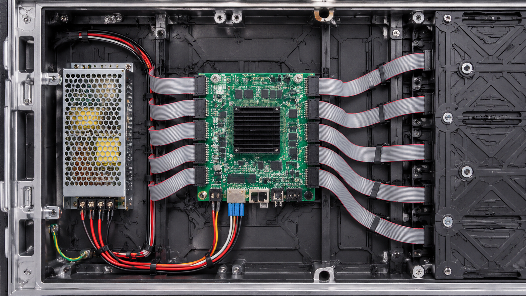
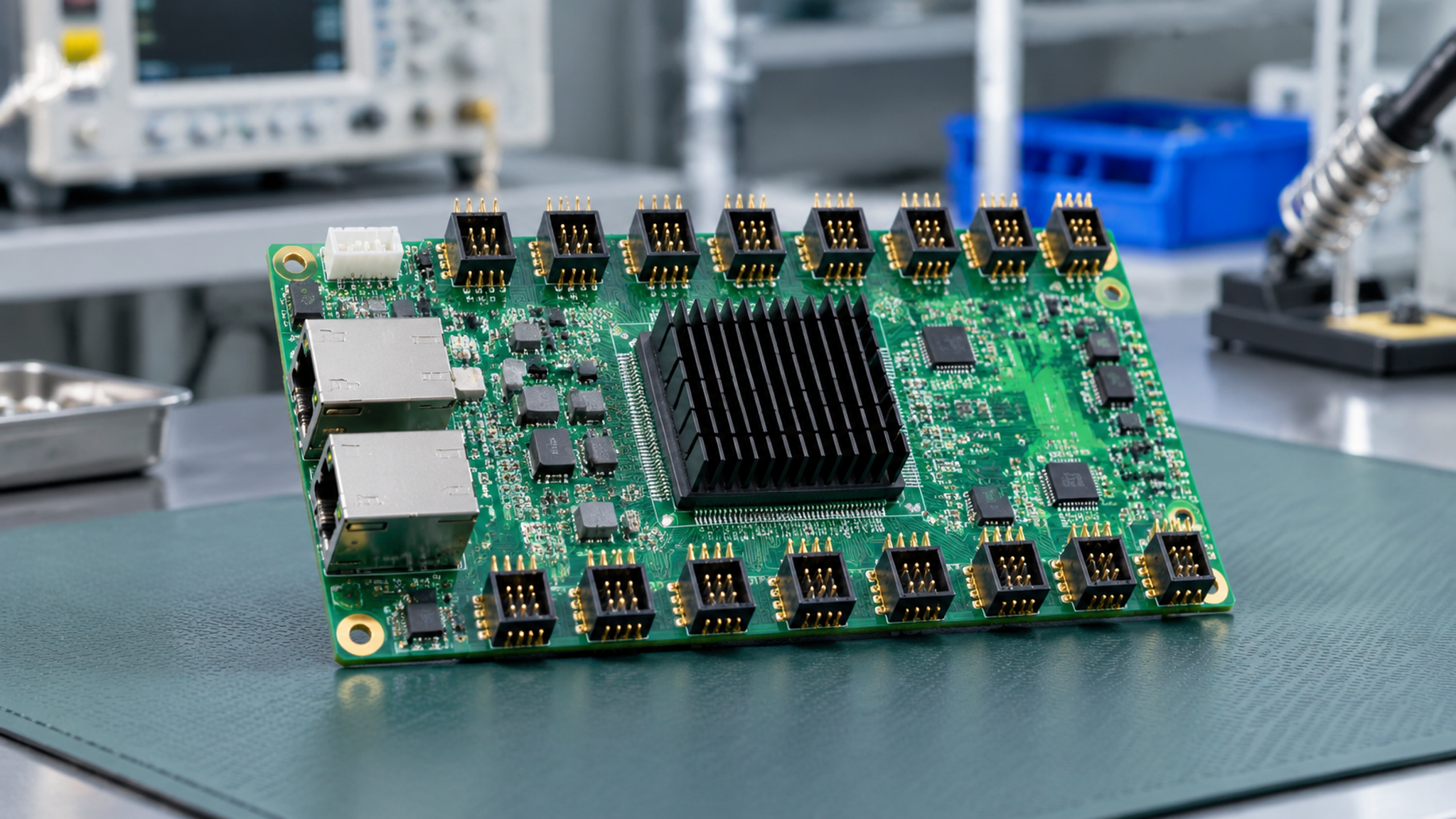
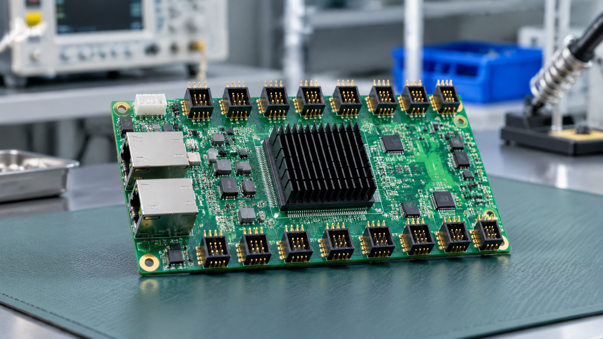
LED display cabinet integration requires receiving cards that balance high pixel density, versatile hub compatibility, and stable transmission redundancy. The NovaStar MRV412-N provides an integrated solution by embedding 12 direct HUB75E headers directly onto the circuit board, eliminating external adapter hub boards and minimizing internal cabinet wiring failure points.
Key architectural advantages of the NovaStar MRV412-N include:
• High Pixel Loading Density: Drives up to 512 by 512 pixels per card with 24 parallel RGB data groups, providing ample bandwidth for fine-pitch and standard pixel pitch modules.
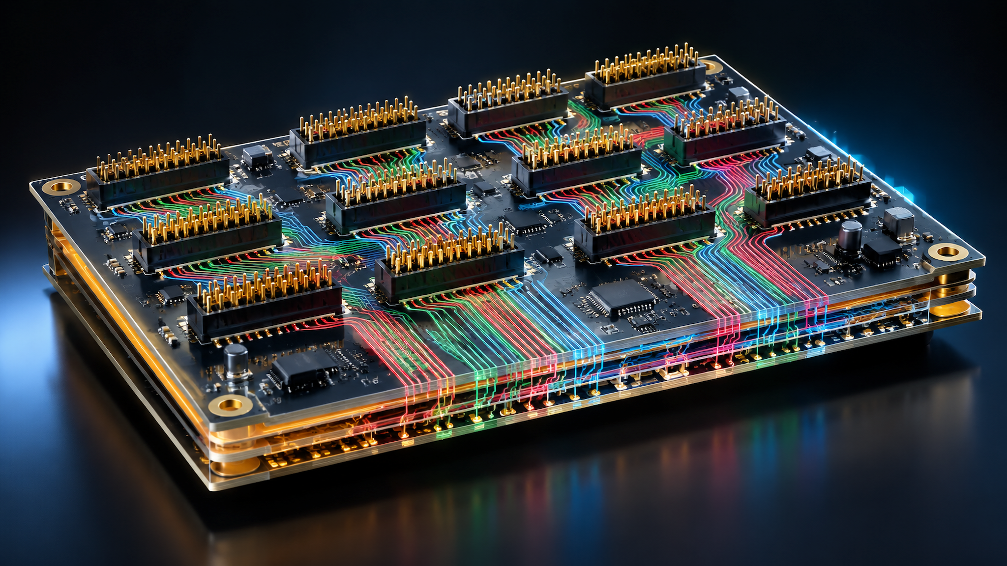
• Direct HUB75E Integration: Direct on-board 12 times HUB75E 16-pin connectors allow direct ribbon cable connection to LED display modules without adapter boards.
• Advanced Pixel-Level Calibration: Works with NovaLCT and NovaCLB to execute pixel-by-pixel luminance and chrominance calibration, ensuring perfect visual uniformity.
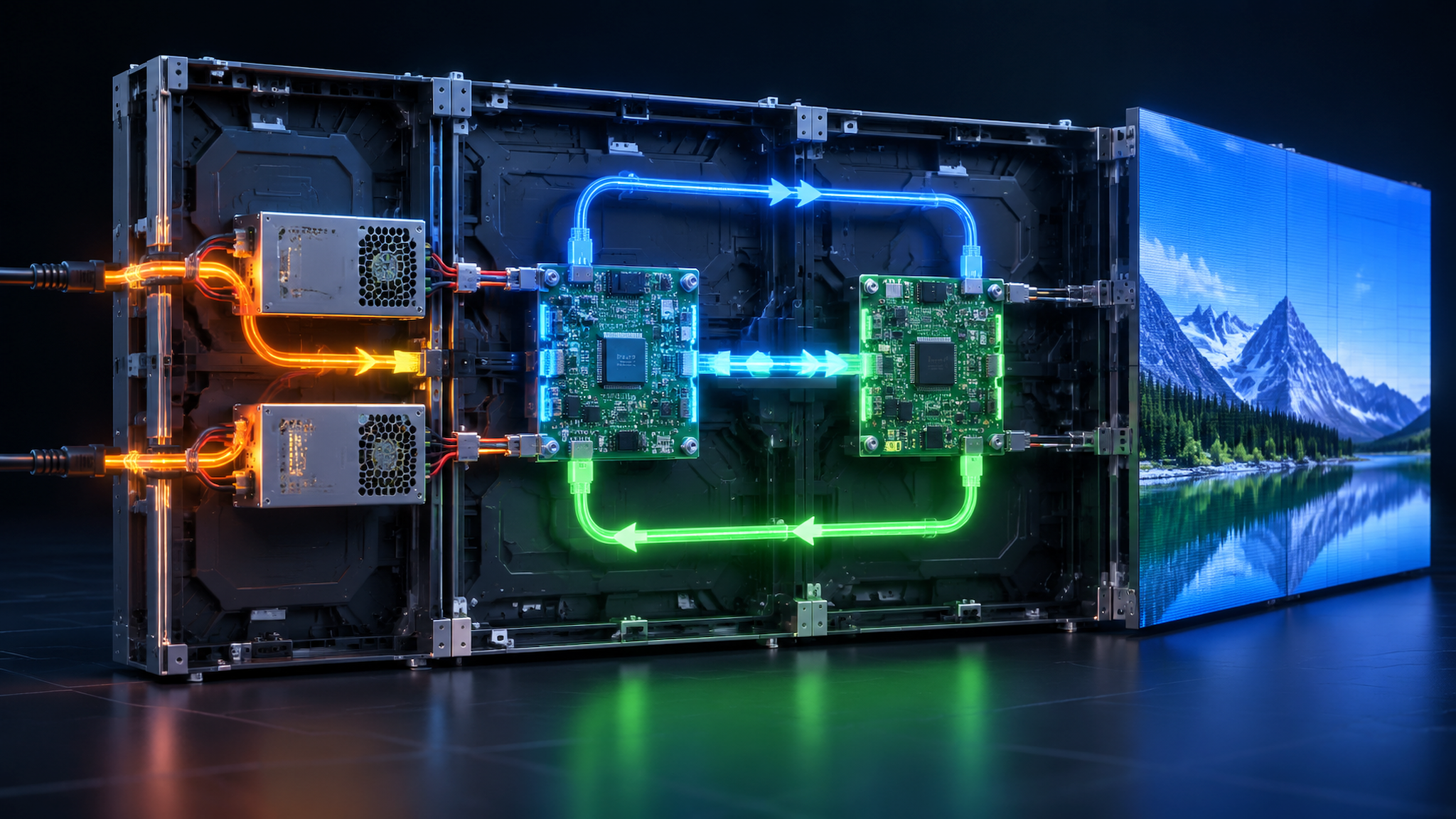
• Multi-Tier Hardware Redundancy: Supports dual-card hot backup, dual-power redundancy, and Gigabit Ethernet loop failover to maintain uninterrupted display operation.
2. Core Technical Parameters and Engineering Specifications
The technical parameters of the NovaStar MRV412-N are synthesized in the following master table based on verified manufacturer engineering documentation.
Technical Dimension | MRV412-N Hardware Specification | Engineering Notes and Operational Scope |
Maximum Loading Capacity | Up to 512 by 512 Pixels at 60Hz | Loading capacity depends on module driver IC and scan frequency (typical 512 by 384 pixels) |
Parallel RGB Data Groups | 24 Groups of Parallel RGB Data | Two parallel RGB data channels routed per HUB75E connector header |
Output Interface Connectors | 12 Standard HUB75E 16-Pin Headers | Gold-plated dual-row pin headers for direct ribbon cable interconnect |
Ethernet Communication Ports | Dual Gigabit RJ45 Ports (Port A and Port B) | Supports auto-sensing Gigabit Ethernet with loop backup redundancy |
Input Voltage Range | 3.3V to 5.5V DC Universal Input | Rated operating voltage 5.0V DC with low-voltage stability protection |
Rated Current and Power | Rated Current 0.5A to 0.6A (Power 2.5W to 3.0W) | Energy-efficient operation reduces internal cabinet heat dissipation |
Pixel Calibration Support | Pixel-Level Brightness and Chroma Calibration | Eliminates color non-uniformity across batch-mixed LED lamp beads |
Quick Seam Correction | Chroma and Brightness Seam Adjustment | Eliminates dark and bright seam lines between adjacent display modules |
3D LUT Color Management | Supported via NovaLCT Configuration | Applies customized color profiles for broadcast and commercial standards |
Hardware Health Monitoring | Temperature and Input Voltage Monitoring | Real-time telemetry reported back to NovaLCT and VNNOX platforms |
Board Physical Dimensions | 145.7 mm by 95.5 mm by 18.0 mm (Weight 100g) | Standard mounting holes compatible with universal LED cabinet brackets |
Operating Environment | Temperature Minus 20 to Plus 70 Degrees C | Humidity 10 to 90 percent RH non-condensing industrial rating |
 3. Hardware Interface Layout and HUB75E Pinout Topologies
The MRV412-N PCB architecture consolidates power, communication, and module drive lines into structured zones:
A. HUB75E 16-Pin Connector Pinout: Each HUB75E 16-pin connector provides standard pinout definitions: Pin 1 (R1), Pin 2 (G1), Pin 3 (B1), Pin 4 (GND), Pin 5 (R2), Pin 6 (G2), Pin 7 (B2), Pin 8 (E), Pin 9 (A), Pin 10 (B), Pin 11 (C), Pin 12 (D), Pin 13 (CLK), Pin 14 (LAT), Pin 15 (OE), Pin 16 (GND).
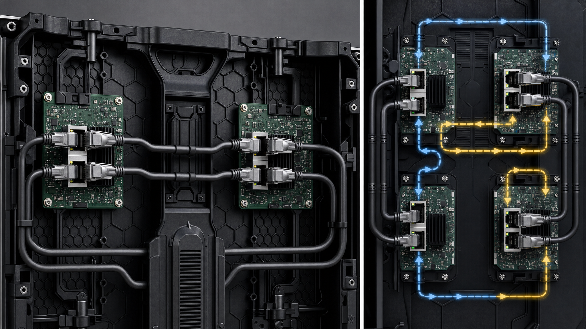
B. Gigabit Ethernet Loop Ports: Dual shielded RJ45 ports (Port A and Port B) auto-sense Gigabit data. In loop backup wiring, Port A serves as primary signal ingest while Port B links back to the sending controller backup chain.
C. Power Supply Ingress: Standard 4-pin DC power connector (VCC and GND pairs) accepts 3.3V to 5.5V DC from the cabinet switching power supply.
4. Software Ecosystem, Firmware Upgrading, and Setup Workflow
Commissioning the MRV412-N utilizes the NovaLCT configuration software suite for hardware programming and calibration:
• NovaLCT Configuration Platform: NovaLCT is used to generate or load module configuration files (RCFGX), configure cabinet scanning parameters, and burn settings to non-volatile flash memory.
• Firmware Upgrade Deployment: Firmware packages (.npk or .dat formats) are deployed through NovaLCT under the Receiving Card Upgrade menu with automated version verification.
Engineering Commissioning Workflow Step-by-Step
Step 1: Physical Mounting and Cabling — Mount MRV412-N on cabinet plate, connect 5V DC power, connect HUB75 ribbon cables from ports J1 through J12 to display modules, and connect Ethernet Cat6 cables.
Step 2: NovaLCT Detection and Login — Launch NovaLCT, log in under Advanced User mode (admin), and verify communication with the receiving card.
Step 3: Configuration File (RCFGX) Loading — Load pre-tested cabinet configuration file (RCFGX) or generate scanning parameters for the specific driver IC, send to hardware, and save to flash.
Step 4: Screen Pixel Mapping — Map cabinet layout coordinate positions in the Screen Configuration tab to establish multi-cabinet canvas display.
Step 5: Loop Redundancy Verification — Connect backup Ethernet cable to form redundant ring, disconnect primary line, and verify seamless failover.
 5. Multi-Scenario Engineering Application Analysis
The versatility of the MRV412-N enables deployment across mainstream LED display sectors:
Scenario 1: Indoor Commercial Fine-Pitch Displays — Driving high-refresh fine-pitch modules (P1.56, P1.875) with calibrated color uniformity for corporate meeting rooms and retail showcases.
Scenario 2: Outdoor Advertising Billboards — Powering large-format advertising screens with temperature and voltage telemetry for 24-hour outdoor reliability.
Scenario 3: Stage Rental and Touring Events — Mounted in 500 mm by 500 mm die-cast aluminum rental panels, utilizing quick-seam correction and pre-stored logo graphics for live events.
6. Cross-Model Horizontal Comparison and Benchmarking Matrix
The following matrix benchmarks the MRV412-N against sibling NovaStar receiving cards to guide hardware selection.
Technical Dimension | NovaStar MRV412-N | NovaStar MRV416 | NovaStar MRV366 | NovaStar MRV336 | NovaStar Armor A5s Plus |
Maximum Loading Capacity | 512 by 512 Pixels | 512 by 512 Pixels | 512 by 256 Pixels | 256 by 226 Pixels | 512 by 512 Pixels |
On-Board HUB Connectors | 12 Standard HUB75E Headers | 16 Standard HUB75E Headers | 12 Standard HUB75 Headers | 12 Standard HUB75 Headers | High-Density Molex Connector |
Parallel RGB Data Groups | 24 Parallel RGB Groups | 32 Parallel RGB Groups | 24 Parallel RGB Groups | 24 Parallel RGB Groups | 32 Parallel RGB Groups |
Pixel-Level Calibration | Brightness and Chroma Calibration | Brightness and Chroma Calibration | Brightness and Chroma Calibration | Brightness and Chroma Calibration | High-Precision 18-bit Plus Chroma |
HDR and 10-Bit Color Depth | Standard 8-Bit Processing | Standard 8-Bit Processing | Standard 8-Bit Processing | Standard 8-Bit Processing | Full HDR10 and 10-Bit Support |
Form Factor Enclosure | Bare Board (145.7 mm by 95.5 mm) | Bare Board (145.7 mm by 95.5 mm) | Bare Board (145.7 mm by 95.5 mm) | Bare Board (145.7 mm by 95.5 mm) | Compact Card (70.0 mm by 45.0 mm) |
Target Application | Indoor and Outdoor Commercial Displays | High-Density Module Cabinets | Standard LED Billboards | Legacy Display Upgrades | High-End Broadcast, XR Studios |
7. Frequently Asked Questions (FAQ) and Procurement Guidelines
Q1: HUB75 vs HUB75E Compatibility — Question 1: What is the difference between HUB75 and HUB75E interfaces on the MRV412-N?
Answer: HUB75E introduces an extra E line signal on Pin 8 to support 1 to 32 scan rate display modules, whereas legacy HUB75 supports up to 1 to 16 scan rates.
Q2: Firmware Recovery Protocol — Question 2: How can an engineer recover an MRV412-N card if a firmware upgrade is interrupted?
Answer: The MRV412-N integrates dual-boot flash memory. If an upgrade fails, power-cycle the card and re-flash the factory firmware through NovaLCT.
Q3: Calculating Receiving Card Count — Question 3: How is the number of MRV412-N receiving cards calculated for a video wall?
Answer: Divide the total screen resolution by the card capacity (512 by 512 pixels maximum), accounting for individual cabinet boundaries.
Q4: Mixed Card Deployment — Question 4: Can MRV412-N cards be mixed with older MRV336 cards in the same display?
Answer: It is strongly recommended to use identical receiving card models within the same screen to ensure matching gamma curves and scan timings.
Procurement Inspection Checklist: Verify genuine NovaStar holographic labels, confirm batch firmware consistency, inspect gold-plated HUB75E pins, and allocate 3 to 5 percent spare cards per project.