
LED Black Screen: 7 Troubleshooting Checks for LED Walls
A sudden black screen failure on an LED video wall is a critical emergency during live broadcasts, keynotes, and commercial events.
An LED video wall integrates AC power distribution, DC switching power supplies, sender controllers, Gigabit Ethernet lines, receiving cards, and magnetic LED modules. A failure at any point interrupts power or data flow.
Use this 7-step diagnostic checklist to isolate and resolve LED screen blackouts.
```
LED Video Wall Blackout Triage Hierarchy
┌────────────────────────────────────────────────────────────────────────┐
│ 1. Global Blackout (Whole Screen Dark) ──> Main PDU, Sender, Video In │
├────────────────────────────────────────────────────────────────────────┤
│ 2. Cascade Blackout (Chain Dark) ──> Primary Ethernet / Port / Patch │
├────────────────────────────────────────────────────────────────────────┤
│ 3. Single Cabinet Blackout (One Box Dark) ──> 5V Power Supply / RCG Card│
├────────────────────────────────────────────────────────────────────────┤
│ 4. Single Module Blackout (One Tile Dark) ──> HUB75 Ribbon / DC Cable │
└────────────────────────────────────────────────────────────────────────┘
```
---
The 7-Step Diagnostic Protocol for LED Video Wall Failures
```
Systematic 7-Step Troubleshooting Flow
┌────────────────────────────────────────────────────────────────────────┐
│ Check 1: AC/DC Power Infrastructure & Circuit Breaker Verification │
├────────────────────────────────────────────────────────────────────────┤
│ Check 2: Sending Controller Hardware Status & Video Input Lock │
├────────────────────────────────────────────────────────────────────────┤
│ Check 3: Gigabit Ethernet Cable Integrity & Signal Daisy-Chains │
├────────────────────────────────────────────────────────────────────────┤
│ Check 4: Receiving Card Status LEDs & RCFGX Firmware Calibration │
├────────────────────────────────────────────────────────────────────────┤
│ Check 5: Internal HUB75 Ribbons & Board-to-Board Floating Sockets │
├────────────────────────────────────────────────────────────────────────┤
│ Check 6: PC Graphics Card Resolution, EDID, & Canvas Mapping │
├────────────────────────────────────────────────────────────────────────┤
│ Check 7: Redundant Loopback Switching & Fault Bypass Testing │
└────────────────────────────────────────────────────────────────────────┘
```
---
Check 1: AC Power Distribution & DC Switching Power Supplies
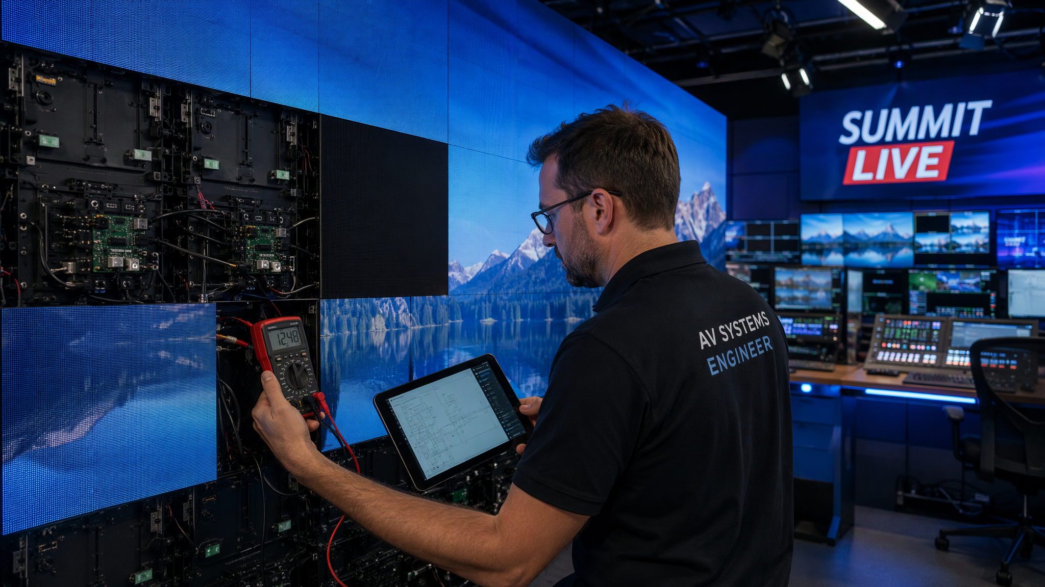
· Main PDU Breakers: Check if the three-phase or residual-current circuit breaker (RCCB) tripped from inrush current.
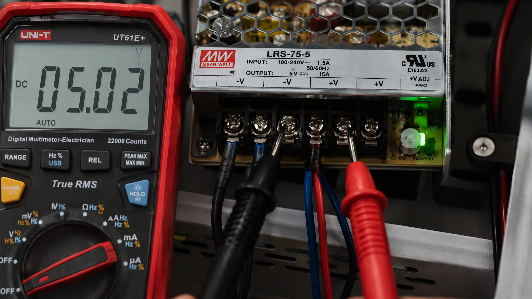
· Cabinet 5V / 4.2V Power Supply: Measure DC output across $V+$ and $V-$ with a multimeter. Normal output is $4.2text{V to }5.1text{V DC} pm 0.1text{V}$; readings below $3.8text{V}$ indicate an overloaded or failed unit.
---
Check 2: Sending Controller Hardware Status & Video Input Lock
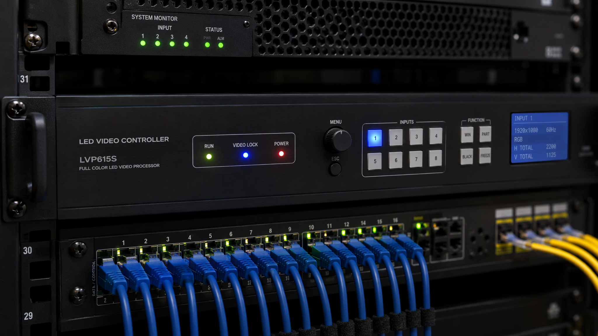
· Power LED (Red): Solid on.
· RUN LED (Green): Blinks rhythmically at $1text{ Hz}$ (1 flash/sec). Fast flashing indicates an FPGA boot error; dark indicates a board crash.
· Input Lock LED (DVI/HDMI/SDI): Solid on. Blinking or off indicates no valid video clock from the media server.
---
Check 3: Gigabit Ethernet Cable Integrity & Signal Daisy-Chains
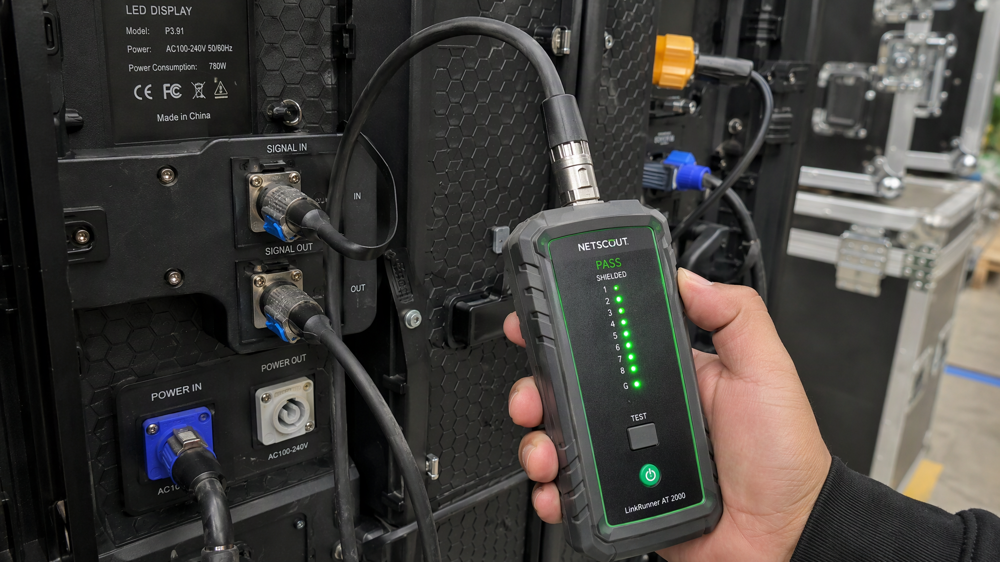
· Cascade Failure: If Cabinet #4 and all subsequent panels (#5, #6) are dark, the fault lies in Cabinet #3's data OUT port, the interconnect patch cable, or Cabinet #4's data IN port.
· Distance Limits: Copper Cat5e/Cat6 runs must not exceed $100text{ meters } (328text{ ft})$. Longer runs require optical fiber transceivers.
---
Check 4: Receiving Card Status LEDs & RCFGX Calibration
· Indicator State: Green RUN flashing at 1Hz indicates normal operation; 4Hz flashing indicates missing video signal; solid off indicates power failure; solid on indicates crashed firmware.
· Configuration Reload: If LEDs flash normally but modules stay black, reload the backup `.rcfgx` / `.casx` cabinet configuration file via NovaLCT.
---
Check 5: Internal HUB75 Ribbon Cables & Board-to-Board Sockets
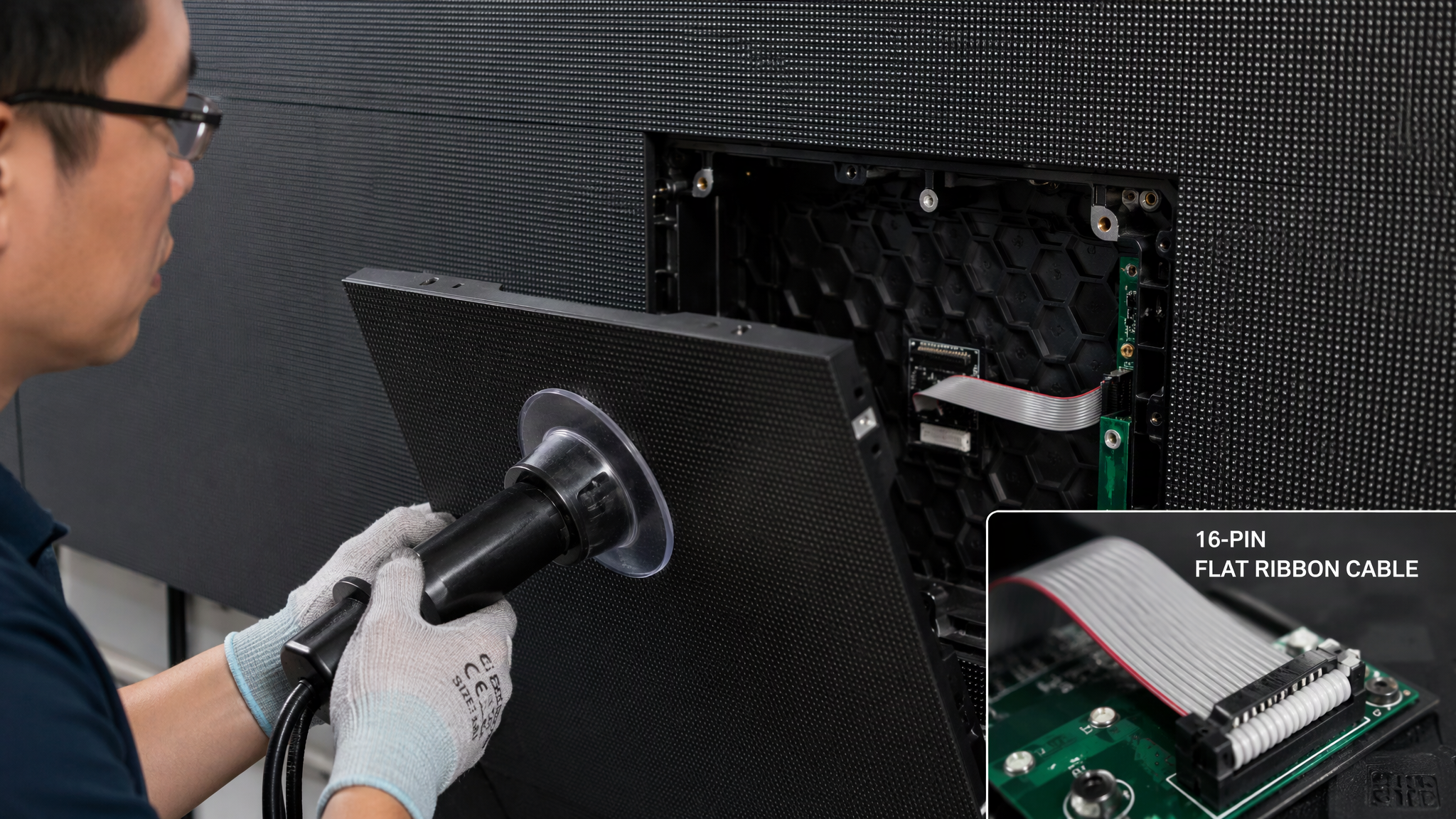
· HUB75 Ribbons: Reseat 16-pin / 26-pin ribbon connectors. Pin oxidation or dislodgement causes single-tile blackouts.
· Board-to-Board Sockets: Extract the module with a vacuum tool and inspect the floating socket for debris, bent pins, or cold solder joints.
---
Check 6: PC Graphics Card Output & EDID Resolution Mapping
· Output Mode: Set Windows/macOS to "Extend Desktop", not "Duplicate" or "Internal Only".
· EDID Handshake: Ensure GPU output matches the sender canvas (e.g., $3840times 2160text{ at }60text{ Hz}$) to prevent dropped video lock.
---
Check 7: Redundant Loopback Switching & Fault Bypass
· Loopback Test: Disconnect the primary Ethernet line; the backup return loop should take over within $le 1text{ frame } (16.6text{ ms})$ with zero blackout.
· Live Bypass: Bridge a dead middle cabinet by running a spare Cat6 jumper from the preceding working cabinet's OUT port directly to the next cabinet's IN port.
---
LED Black Screen Troubleshooting Master Decision Matrix
Failure Symptom | Most Probable Root Cause | Immediate Diagnostic Action | Corrective Resolution |
Entire Screen Completely Black | Tripped main AC breaker; sender crashed; no video input | Check PDU breakers; check controller Power and Video Lock LEDs | Reset breaker; reconnect HDMI/DP source; power cycle controller |
One Vertical Column Dark | First cabinet in column lost power; blown primary Ethernet cable | Inspect Ethernet link LED on first dark cabinet; check AC loop cable | Replace main Cat6 feed line; replace blown AC input power jumper |
Cascade Blackout (Cabinet #N onward) | Data OUT port on Cabinet #N-1 failed; bad patch cable | Check link LEDs on #N-1 OUT and #N IN ports; swap patch cable | Replace patch cable; bridge signal using secondary loop port |
Single Cabinet Completely Black | Blown 5V switching power supply; receiving card crashed | Measure DC voltage across power supply ($4.2text{V}-5.0text{V}$); check RCG RUN LED | Replace 5V power supply unit; reload .rcfgx configuration file |
Single Module (Tile) Dark | Loose HUB75 ribbon; disconnected DC power harness | Extract magnetic module; check 16-pin ribbon and 5V 4-pin harness | Reseat ribbon cable; replace damaged module tile with spare |
Random Flashing / Black Blinks | Loose Ethernet connector; cable length $>100text{m}$; grounding hum | Check cable run distance; verify electrical grounding continuity | Shorten cable run; install fiber converter; tighten ground lugs |
---
Five Golden Field Rules for AV Technicians
1. Always Carry a Calibrated Multimeter. Measure $5text{V DC}$ output across terminals before replacing hardware.
2. Store Backup `.rcfgx` Files on USB Drives. Keep an uncorrupted copy of cabinet configuration data in the control rack.
3. Never Pull Ribbon Cables by the Wires. Always grip the plastic IDC housing to avoid fracturing crimp contacts.
4. Enforce Main and Backup Dual-Loop Cabling. Connect the return loop back to the controller for instant failover.
5. Keep 5% Matching Spare Parts On-Site. Stock 5 modules, 2 power supplies, 2 receiving cards, and patch cables for fast swaps.
---
Frequently Asked Questions
Why did my LED wall go black while the controller shows a green RUN light?
A 1Hz RUN light proves controller CPU activity, but the video input light may be dark (no PC signal), or output mapping may be off-canvas.
How do I fix a single dark module tile during a live event?
Use a vacuum tool to pull the magnetic module forward, inspect the 16-pin ribbon cable and DC power harness, and swap in a matching spare module in under 30 seconds.
Can a bad Ethernet cable damage an LED receiving card?
No. Standard Gigabit differential signals cannot damage receiving cards. However, PoE injected by incorrect network switches will destroy them.
Why does my LED video wall flicker and go black intermittently?
Intermittent blackouts are usually caused by an Ethernet run exceeding $100text{ meters}$, loose RJ45 connector crimps, or ground loop noise.
---
Final Thoughts
Diagnosing LED video wall blackouts requires a structured top-down approach: verifying power, controller inputs, network transmission lines, receiving cards, and module interconnections. Following this 7-step checklist guarantees swift recovery and uninterrupted uptime.


